First of all, electrosatic actuators dislike stray charge that may come from airborne particule, or by improper grounding. To lessen these effects you must ground everything than can be grounded and leave a ground plane just below the actuator. If you forget this you may expect unreliable behaviour and, for example, actuator working for a while and then stopping (build-up of charge in insulating layer that stick the actuator), or actuator operation varying with humidity level (a film of water helps to reduce the static charge by increasing the conductivity) or even actuator not working at all... Actually even with well grounded structure you may already be affected by these problems...
DC polarization
For a comb-drive actuator, where the force does not change with the displacement, and with a linearly increasing restoring force (ie, a spring) it means that the displacement also increases with the square of the voltage. Thus take care not to increase to rapidly your voltage:, when you go from 1 to 10 V, you increase the force by a factor of 100 and at 31.5V it is a factor of 1000!
Moreover, for a gap-closing actuator, where the force increase quadratically with the displacement, associated with a linearly increasing restoring force (ie, a spring), after the actuator has moved 1/3 of the initial gap width, it will snap through and 'close' the gap. This may cause a short-circuit if no insulator or landing point has been designed. However this problem does not always appear and I've noted that for doped polysilicon actuator short-circuit do not appear for moderate voltage, presumably because of the native oxide layer and the large rouhghness of the side that yields a very small contact area.
And finally, if the structure does not move? Hum, hum. Actually this is the most common case :-( Then either your structure is stuck (check your release process, and why not try SAM coating?) or more probably the voltage is not high enough (Actually, and to be honest, it means that your structure is too stiff or the electrodes surface too small :-). Then, you need a DC power supply which can deliver higher voltage or you may try to excite your structure by applying AC signal, which will give you more information on your structure.
AC polarization
Introduction
The main interest of applying AC voltage to an electrostatic actuator is the measurement of its resonnant frequency. But it may also be simply used to check if a stiff structure is moving, because at the resonnant frequency the displacement is increased by the Q factor of the structure, often more than ten, and more than enough to see something with the optical microscope without investing in laser vibrometer...Applying a pure sinusoidal voltage
As we have already pointed out the force delivered by an electrostatic actuator vary with the square of the voltage. Thus what happen if we apply a sinusoidal voltage V = V0 sin(wt + Ø ) to it? We have:What happen if we add an offset voltage to the sinusoidal voltage?
We return back to the expression of the force, which gives in this case:F ~ ½V0² + V1² + 2V0V1sin(wt + Ø ) + ½V0²sin(-2wt - 2Ø + ¶/2)
And what about a square, triangular, or patatoidal voltage?
Actually the whatever periodic signal you use may be decomposed in Fourier series and, for example, you will find that a square signal is the sum of sinusoidal signals whose pulsations ar an odd multiple of the original pulsation (ie, the odd harmonics) and whose amplitude decrease as the inverse of the rank of the harmonic. Generally, signals will have a more complex decomposition, including odd and even harmonics with amplitude varying as a complex function of the harmonic rank (it is similar to the signal with offset case, where we had only the two first harmonics).Then the force is once more proportional to the square of the signal and thus it will have frequency components which will be a multiple of the original signal frequency, and including this frequency. The amplitude of the different harmonics will depend on the signal and may be computed using Fourier analysis. However it is not a simple calculus, as not only square of the signal will appear but also cross-product between harmonics which result in the generation of signal having a frequency corresponding to the difference of the two signal mixed.
Practically you will see your structure being excited in resonance with many different frequencies that you may mistakenly take for higher order mode. However, if you find that they are an integer multiple of the lowest resonnance frequency (which will be equal to the signal frequency and not twice its value as with a pure sinusoidal signal)... then it is most probably just the harmonics of the AC signal that excite one after the other the resonance of your structure.
Conclusion
Generally speaking, except for special case, you should avoid signal other than sinusoidal when you want to measure resonnant frequency of your structures. If you want to use synchronous detection of displacement you need to add an offset voltage, preferably with an amplitude much larger than the amplitude of the sinusoidal component, and the structure will be driven at the same frequency than the AC signal. If you use a pure sinusoidal signal (without offset) the structure will be driven at a frequency twice that of the AC signal.A ±30V voltage amplifier
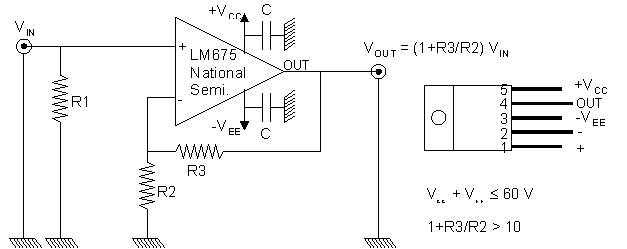
R1 = 18kO; R2 = 1.2kO; R3 = 12k; C = 0.1µF, two BNC plugs for VIN and VOUT and three 4mm socket for VCC, VEE and the ground.
We obtained a gain of 11, an output voltage of 58Vpp (VCC = VEE = 30V), and a bandpass of about 1MHz for small signal but limited by the slew rate (typical 8V/µs, but larger for our component :-) for large output swing (±29V) to about 80kHz without too much distorsion. For most structure 80kHz is more than enough, but don't try to power your 1MHz resonator with this device... you won't get more voltage than with the function generator alone :-)